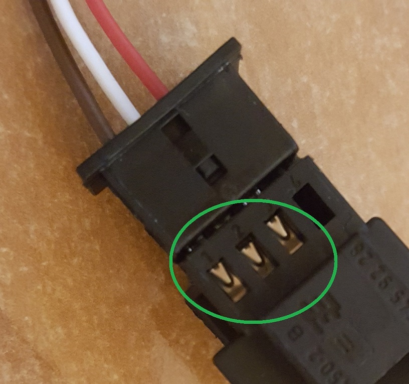
The procedure is very simple. To change the connectors you need a small screwdriver or a knife.
To remove the wire from the connector you need to push the pin at the top of the connector (marked with a circle on the photo 1) and gently pull out the wire from the hole. In this video we showed how to do that: https://www.youtube.com/watch?v=8HCkWPbN6DU
Attention if you are removing the wires from the connector in order to place them in other connector! Emulator's wires need to be inserted in the same positions as the wires in the original conenctor. Emulator's red wire needs to go the to the pin hole where the red wire of the original connector was inserted. White wire needs to go to the the same hole where the original white wire was, etc. You need to replace all wires in the same way, into the same positions.
We suggest removing the red wire from the original connector first and insert emulator’s red wire in its place. Then remove the brown wire and insert emulator's brown wire, etc. This way you will avoid inserting the wires to the wrong holes.
Photo 1. Pins that need to pushed using a small screwdriver or a knife.

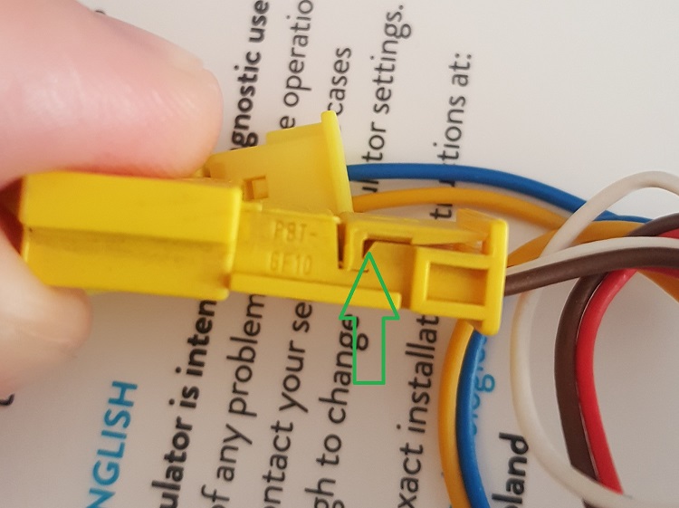
Some of the connectors have an additional plastic element that also holds pins after releasing them from the connector. We have marked it on Photo 2. This plastic element protects the wires from accidental removal. In that situation you need to lift up that plastic element and push the pin showed on the Photo 1. The pin will move to the place which was covered by the plastic element. You need to push the pin again and gently pull out the wire from the connector. Our video shows how to lift up the plastic element. The listing procedure starts from 0:48: https://youtu.be/8HCkWPbN6DU?t=48
Photo 2. Additional plastic element that needs to be lifted marked with an arrow.

